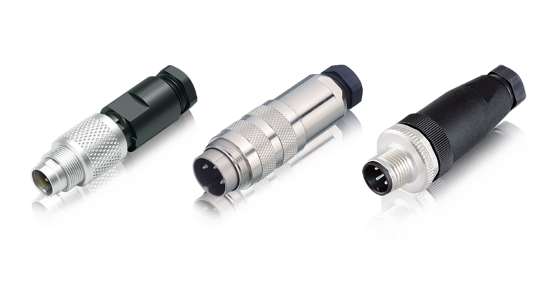
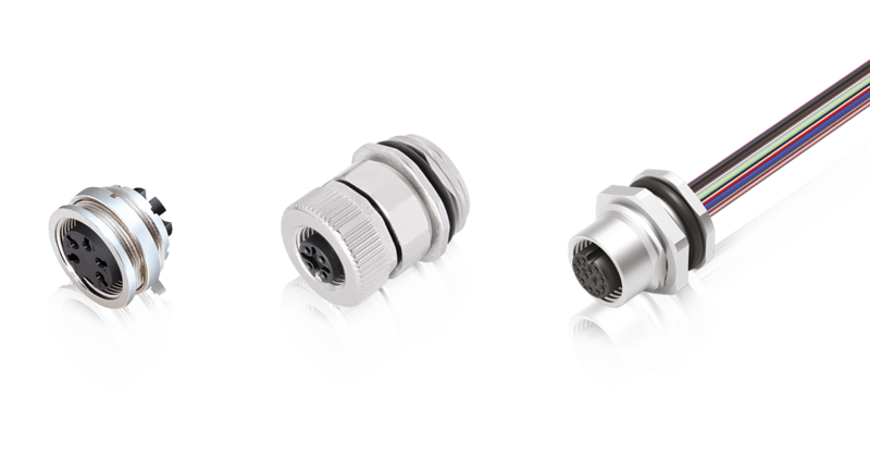
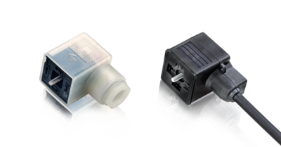
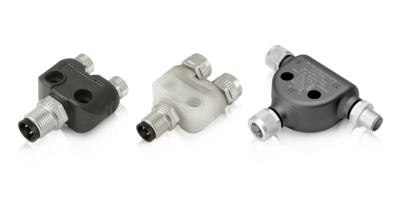
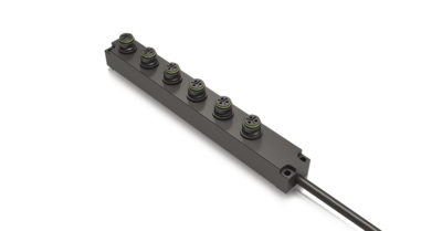
The connector type can be used to distinguish our products for installation in a device housing from cable parts. The connector type describes the difference between connectors that are mounted on enclosures, connectors that are mounted on cables, and other connection componentsdistributing signal and power.
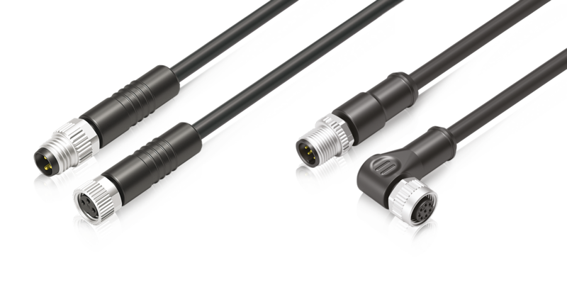
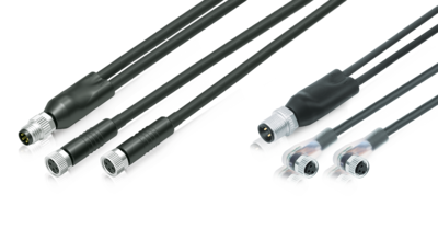
A connector consists of the male part (pin) and the female part (socket). Depending on the design, the male or female part is either permanently installed or are located at the end of a cable.
Electromagnetic compatibility (EMC) means that a connector is shielded or shieldable. This is required when it is necessary to protect the signals or data conducted by the connector, as well as to protect external devices, from disturbance due to electromagnetic effects.
The degrees of protection according to IEC60529 apply to various articles and provide information on protection against the intrusion of water and solids such as dust.
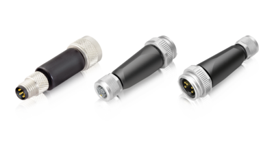
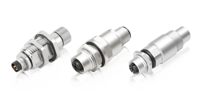
Depending on the area of application or requirements, connectors are made of different materials. We offer metal and plastic housings for our items as the housing material.
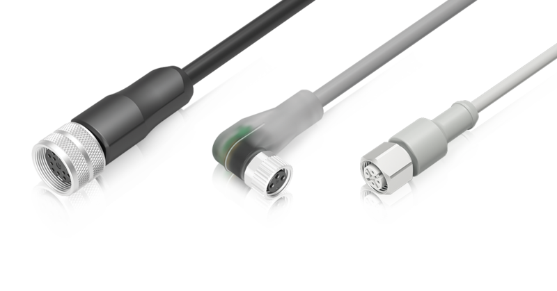
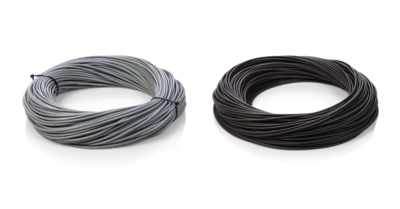
Our items with molded or pre-assembled cables have different cable lengths. It describes the length of the cable from the end of the connector. If the desired cable length is not included, please contact our sales department.
The stranded wire is an electrical conductor consisting of thin individual wires and is therefore easy to bend. The individual wires of the stranded wire are usually enclosed in a common insulating sheath and come in different wire lengths.
The connection cross-section defines the possible size of a stranded wire on a contact in the flange or field attachable connector. Cross-sections from 0.08mm² to 6.0mm² are possible here. Since various industry are also using wires according to the American Wire Gauge (AWG), both units are reflected.
Field attachable connectors can be assembled with different cables. The cable aperture indicates the possible cable diameters that can be used on an article.
The contact surface refers to the plating of the contacts (e.g., gold or silver) and affects conductivity, corrosion resistance, and the service life of the circular connector.