Menu
Subminiature connectors
Filter products
Connector type
The connector type can be used to distinguish our products for installation in a device housing from cable parts. The connector type describes the difference between connectors that are mounted on enclosures, connectors that are mounted on cables, and other connection componentsdistributing signal and power.
Number of contacts
This indicates the number of contacts the connector has.
Gender
A connector consists of the male part (pin) and the female part (socket). Depending on the design, the male or female part is either permanently installed or are located at the end of a cable.
Version
The choice of version allows the definition of the cable outgoing.
Locking Type
The locking system describes how the pin and socket elements are joined.
Termination
The termination type determines how cables, single wires or PCBs can be joined with the connector.
Shielded Option
Electromagnetic compatibility (EMC) means that a connector is shielded or shieldable. This is required when it is necessary to protect the signals or data conducted by the connector, as well as to protect external devices, from disturbance due to electromagnetic effects.
IP-Rating
The degrees of protection according to IEC60529 apply to various articles and provide information on protection against the intrusion of water and solids such as dust.
Material of housing
Depending on the area of application or requirements, connectors are made of different materials. We offer metal and plastic housings for our items as the housing material.
Rated current
The rated current is the electrical current that is assigned to the connector.
Rated voltage
The rated voltage is the electrical voltage assigned to the connector.
Locking material
Depending on the technical requirements or performance data of the connector, the locking mechanism is made of plastic or metal.
Mounting orientation
The mounting orientation for flange connectors defines the side from which an item can be mounted.
Mounting thread
There are different thread sizes for the device-side connection, depending on the design. These are available in different variants.
Cross section
The connection cross-section defines the possible size of a stranded wire on a contact in the flange or field attachable connector. Cross-sections from 0.08mm² to 6.0mm² are possible here. Since various industry are also using wires according to the American Wire Gauge (AWG), both units are reflected.
Cable outlet
Field attachable connectors can be assembled with different cables. The cable aperture indicates the possible cable diameters that can be used on an article.
Series
The series indicates the product category of binder circular connectors and serves as a guide for selection.
Contact Plating
The contact surface refers to the plating of the contacts (e.g., gold or silver) and affects conductivity, corrosion resistance, and the service life of the circular connector.

Subminiature bayonet connector IP40

The bayonet connectors from binder are particularly suitable for applications requiring high connection reliability and mechanical stability. Equipped with a practical bayonet locking mechanism, they enable a fast, reliable, and user-friendly connection solution.

The 5-pin version provides a compact solution for applications with multiple connections in limited space, while the 7-pin variant offers extended connection options for more complex circuits.

Bayonet Connector IP40

As part of the subminiature series, these bayonet connectors are ideal for use in confined spaces where reliability and performance are critical. The 710 series is known for its high quality and durability, making it the preferred choice of engineers and technicians in automation technology, Medical Grade technology, and other demanding fields.

The 710 series includes cable and panel mount connectors with degree of protection IP40. They are available in versions with 2 to 8 gold-plated contacts and are designed for a rated current range of 1 A to 4 A at 125 V.

>With the 710 series bayonet connectors, binder offers a high-performance and maintenance-friendly interconnection solution. The simple installation and maintenance of the connectors helps reduce operating costs and increase process efficiency. The components feature a robust plastic housing, a reliable bayonet locking system, and solder termination. The supported conductor cross-section ranges from 0.14 mm² to 0.25 mm². The connectors are designed for a temperature range from -40 °C to +85 °C.

The bayonet connectors from binder therefore provide a reliable and durable solution for industrial applications with high demands on connection technology.
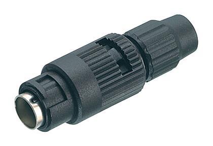
Overview of all bayonet connectors

+65 6513 9466 Contact form